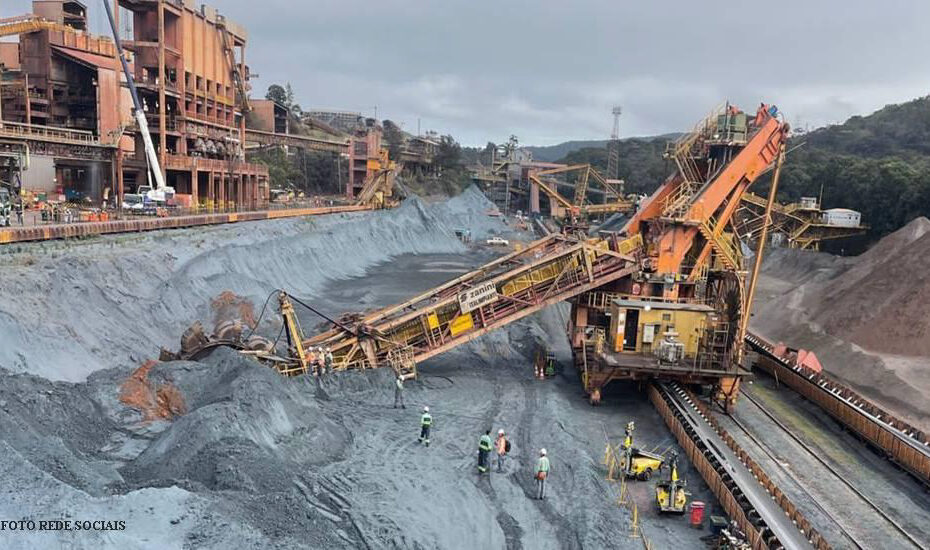
On the 24/07/2023, an incident with a bucket wheel reclaimer halted operations at one of the biggest iron ore producers in the world. Luckily, no one was severely hurt; the operator was sent to hospital and is in good condition. An investigation is underway to determine the cause of the accident; however, all indicate that the boom suspension ropes failed.
Suspensions are critical members for balance machines as they:
- are always in tension: prone to crack propagation;
- are in a majority of the cases, non-redundant: A failure of the component will lead to the failure of the equipment;
- hold a boom or counterweight boom: the stability of the machine depends on them;
- in many cases there is an operator sitting on the boom supported by the suspensions;
- are operating in harsh environmental conditions.
Structural member with such characteristics are often referred as Fracture critical members and are treated differently from the rest. As an example, their inspection regime and fabrication requirements are stricter than other structural members are. To decrease the likelihood of failure, engineers, fabricators, and operators have each its share of responsibility to guarantee the required degree of reliability. However, the design is the phase with most potential to make good decisions and avoid future problems.
This article aims to review the main considerations when designing/selecting wire ropes fixed suspensions (stay ropes) in materials handling mobile equipment.
The first choice the engineer needs to make is on what kind of suspension will be used. Historically, suspension made from flat plates with “dog bones” pinned connections have been widely used in material handling mobile equipment.
More recently, stay ropes are being preferred, as they are cost-effective; reliable; and lighter when compared to the flat plate suspensions. In balance machines, weight management is crucial, making the selection for wire ropes an attractive option, especially on the boom side.
Type of ropes
Different rope construction will have different strengths, corrosion resistances, and of course, different price.

Spiral strand ropes (OSS) are build up with independent layers of helically arranged round wires. They are widely used as structural ropes.

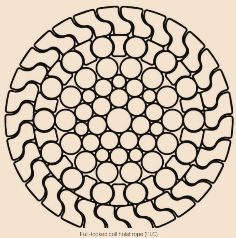
Full locked coils (FLC) will have higher breaking loads; higher modulus of elasticity and better performance in corrosive environments as the interlocking z shaped wires at the outer layer protects the inner layers.
Strength
The resistance of the stay ropes are associated with the breaking load and limitation to the elastic limit (proof load).
FEM – Section II requires a minimum safety factor of 3 against the breaking load for main and additional loads. AS4324.1 requires a minimum safety factor of 4 (special load cases included) for an integral system and 2 after failure of one suspension.
Serviceability
The level of stresses on the suspension ropes has to be limited for many reasons:
- to keep stresses in the elastic range for the relevant design situations during construction and in the service phase;
- to limit strains such that corrosion control measures are not affected, i.e. cracking of sheaths, hard fillers, opening of joints etc.;
- to cater for uncertainty in the fatigue design.
The above is met if the stresses on the cable are kept below 0.5 x breaking strength as a minimum. The required safety factors required by the balance machine standards will guarantee the above.
Vibration induced by the wind is in general not a problem for ropes in the length range used in mobile machines. Nevertheless, it should be checked by the engineer.
EN 19993-1-11 recommends that measures should be taken to avoid over1apping of frequencies, i.e. situations where the cable stay’s frequency of excitation Q is within 20 % of the structure’s frequency.
Fatigue
Mobile machines are subject to variable loading from product variation on the boom, dynamic effects from star/stop movements, and digging forces. Fatigue failure of cable systems usually occurs at anchorages, saddles or clamps.
EN1993-1-11 suggests the fatigue resistance should be determined by testing the actual situation to define the detail category. In absence of tests, it gives categories based on the type of rope. The latter is most of the time sufficient since suspensions for the balance machines are in general straight and has no features/attachments.
Due to the high safety factors used in the static design of ropes, fatigue requirements are not difficult to be met.
Corrosion
Corrosion protection has to be applied to all suspensions system. In general, each individual steel cable wire is galvanized with zinc or a zincaluminium alloy. A second corrosion protection system such as an interior cable filling or an exterior cable coating may be required.
Cable terminations are galvanized or zincmetalized.
Additional corrosion protection where dirt and moisture may accumulate on the terminations should be provided. This protection may consist of polyethylene sheathing or zinc rich paint.
Redundancy
Every effort should be made to have a redundant suspension rope system. Although all caution can be exercised on the paper, the harsh environmental conditions where materials handling equipment works, the reality of the operator, and maintenance costs will always play an important role in the level of care these elements receive.
In this regard, the Australian Standard for mobile materials handling equipment (AS4324.1) is a step ahead. As an answer to previous incidents, machines designed for Australian market shall have duplicated suspension ropes on each side of the boom (the same is required for the luffing system, be it hydraulic or which operated).
Designing redundant suspension can be challenging due to geometry and space constrains. The ropes need to be equalised to guarantee the intended load share. The engineer shall analyse the impact of the snapped rope scenario on the structure using appropriate dynamic factors/analysis.
Structural system
Structural systems for mobile machines should be designed as statically determinate whenever possible. This will provide simple and clear load paths for the structural elements, especially the suspensions. In many cases, however, an overdetermined system (e.g. continuous boom with multiple suspensions) will provide structural benefits or is a functional requirement. In those cases, the suspensions will require a tensioning system during construction phase. The engineer needs to specify the amount of load each suspension should be tensioned to under dead loads only.
Different scenarios need to be tested, e.g. during start or stop of production, the product load is only on the back or only on the tip of the boom.
The behaviour of the system will vary on each case and so the “load share” between the suspension ropes and boom structure itself.
Prestreching initially seats the cable wires into a compact cross section to obtain close to an elastic cable behaviour, however, creep will still occur under service loads. For an over constrained system, it means the load on the cables will change and the creep effect may be a design consideration.
General design aspects
- The rope termination shall be positioned to avoid product and moisture build-up.
- Threaded terminations (e.g. turnbuckles)should be avoided. The stress concentrations inherent to the threads associated to corrosion leads to limited fatigue life.
- All suspension terminations shall be accessed from walkways to facilitate inspections and tests.
- The design of the equipment shall allow for a procedure for suspension ropes change-out. The procedure will guarantee the equipment is stable and structurally sound during the works.
- The engineer shall provide information about the inspection regime and required level of inspection/NDT on the equipment manuals.
Conclusion
Stay cables used to support booms in mobile materials handling machine are regulated in the appropriate standards concerning the required safety factors. No further guidance is given and the engineer has the task to select a system that will perform as contractual expectations. This article briefly reviewed the main aspects related to stays cables and suggested concern points to be addressed during the design phase.
References:
FEM – Rules for the design of mobile equipment for continuous handling of bulk materials
AS4324.1 – Mobile equipment for continuous handling of bulk materials.
EN 1993-1-11 -Design of structures with tension components
ASCE/SEI 19-10 – Structural application of steel cables for buildings.
Properties of and Applications with Full Locked
Coil Rope Assemblies Authors: K.-
J. Thiem kai.thiem and M. Bechtold martin
Pedro Paulo Beleigoli – MIEAust CPEng NER
APEC Engineer IntPE(Aus)
pedro.paulo.bel@gmail.com – July 2023
